BALSA WOOD RISING BRIDGE
CWU MET Senior Project 2020-2021
What is the solution to allowing tall vessels to navigate past a vehicle bridge that is less than 10 [ft] above the water? To answer this question, a balsa wood bridge was designed, constructed, and tested. The bridge needed to articulate by mechanical means, allow for travel through the bridge, and be able to withstand ample force while the main structure only being constructed of balsa wood and glue. The project was analyzed in sections. These sections include: the bridge structure and its members, the hydraulic lift, and the pins needed for the bridge and hydraulic lift to operate. The analysis determined that the bridge design would be suitable for the specified requirements. The requirements include: being able to hold 18.9-20 [kg], articulate to 140 [mm], hold the position for 5 seconds through mechanical means, weigh less than 85 [kg] without the articulation mechanism, span a gap of 400 [mm], and allow travel through the bridge without obstruction. Construction of the parts needed to build these sub-assemblies and assemblies was completed first. The bridge structure was then built in sections: the bridge structure sub-assembly, the hydraulic lift sub-assembly, and the bridge assembly. Once built, the balsa wood bridge was tested to make sure it met its objectives. These tests were conducted on an engineering basis, such as the concepts of bending stress, moments, and material properties. The series of tests conducted proved that the final design of the bridge would meet the requirements stated above.
INTRODUCTION
It is often that a bridge will need to allow for two kinds of travel: by boat and by car. Often times the existing road on land is lower than the biggest boat that will need to pass under the bridge. This means the bridge must be able to raise when incoming boat traffic that is larger than the allowing clearance needs to pass. Before large structures are built, there needs to be a prototype on a smaller scale in order to model that the bridge would serve its purpose. Engineering will address the problems that may arise with a rising bridge by finding a solution to how to make the bridge rise without causing unneeded stresses and keeping the bridge light enough to rise without excessive weight.
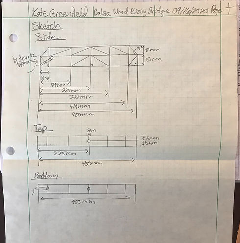
For this project, the bridge will be made exclusively out of Balsa wood and glue, excluding the lifting mechanism. The bridge must raise 50% of it to 140 [mm] and span a gap of 400 [mm]. The bridge must also be able to withstand 18.9-20 [kg] while weighing less than 85 [g], excluding the lifting mechanism
RESULTS
The bridge met all of the specified requirements.
The following were the results of this project:
The bridge can rest flat on steel abutments that cannot withstand lateral force
The bridge road deck is within 12 [mm] of the steel abutments
The bridge is made out of balsa wood and glue without the articulation mechanism
The bridge spans a gap of 400 [mm]
The width of the road deck is 38 [mm]
The road deck is centered on the bridge and is not curved
The hole in the center of the road deck is at the actual center of the road deck and measures to 8 [mm] is diameter
The bridge allows for a 32 [mm] wide by 25 [mm] high testing block to pas through the length of the bridge without instruction
The bridge raises by automated or manual means
The bridge raised 50% of the bridge to 143 [mm]
The bridge weighs 73 [g] without the articulation mechanism
The bridge holds 20 [kg] at the hole in the road deck
These tests are accurate and precise as the tools used for these tests are accurate for the scale of the project. This project and tests could also be repeated to obtain the same results and thus the tests are precise.
These tests are valid and representative as the tests were done indoors at room temperature, which is about the average temperature the bridge would be facing in a real environment. However, since the tests were completed inside, these tests failed to be representative of the outdoor environment with factors such as wind and rain.
The results of these tests are relevant because even though the tests were conducted indoors or the slight chance of tool error, the results proved that the bridge exceeded the requirements and thus would function just the same with slight measurement error in testing or some weather factors, not including extreme weather.
ANALYSIS
REQUIREMENTS
Span an opening of 400 [mm]
Rest on 60 [mm] wide steel abutments that cannot withstand lateral force
The bridge structure, not including the raising mechanism, must not exceed 85 [g] and must be entirely made out of balsa wood and glue
The bridge road deck must be 38 [mm] wide with no openings other than the 8 [mm] diameter hole in the middle for testing
The road deck must be within either 12 [mm] of the abutment level at the outside edge of each abutment or the ends of the bridge, whichever is a shorter distance
The road deck must be centered within the bridge and must be either horizontal or a smooth curve. If the road deck is a smooth curve, the difference in elevation between any two points on the deck must not exceed 25 [mm]
The road deck must be free from obstructions in order to allow a 32 [mm] wide by 25 [mm] high block to pass through
The bridge must raise to lift at least 50% of the road deck 140 [mm] above its original horizontal resting position with 10 [g] added to the lifting mechanism
The bridge must maintain lifted position (without intervention) for the minimum time required for traffic to transverse under the bridge (10 seconds)
The bridge must be able to support a minimum of 18.9 to 20 [kg]
ANALYSIS 1
The base analyses of this project pertain to loadings of trusses. This is a fundamental concept used to solve basic engineering problems. In these analyses the equilibrium equations were used, such as: In analysis 1, which can be found in Appendix A-1 - Bridge Loadings, base reactions were found in the applied loading situation with a safety factor of 1.2. Using a safety factor of 1.2 for the project allows for the design to account for other possible loadings that were not intended, so the bridge does not fail at the maximum required load. By finding the base reactions due to the applied load, it was possible to find the loadings within each member of the bridge through a method of sections.
ANALYSIS 2
In analysis 2, which can be found in Appendix A-2 – Side Loading, the definition of normal stress, Stress = F/A, was applied to a situation if the bridge was side loaded with 10 [kg], as to simulate wind in the real world, in order to find the minimum areas of each member of the bridge corresponding to the direction associated with side loading. In order to find the minimum areas of each member, the yield strength was assumed to be the max stress the balsa wood would take before it would break. The values found in this analysis concluded that all the minimum required areas of the members in the side loading situation were admissible as no balsa wood stock sizes are made that small. This concluded that the only situation that needs to be analyzed is the normal loading situation.
ANALYSIS 3
Analysis 3 evaluated the requirement that the bridge must hold 18.9-20 [kg]. This analysis was conducted using the definition of normal stress, F=sigma/A, to determine the maximum area needed in each member by using the yield strength and to determine the stress of a member given the determined stock size and the bridge loadings found in Analysis 1. This analysis also determined the amount of each stock needed for the project by adding the lengths of all parts. Two extra boards were added to the truss members in case needed because parts don’t fit full length on entire board.
ANALYSIS 4
Analysis 4 evaluated the requirement that the bridge must be held together by glue. This analysis determined the glue to be used on the bridge during manufacturing. In order to determine this, this analysis used the material properties for Gorilla epoxy, Gorilla glue, and wood cement. By using these properties, the area needed for each glue to hold the maximum loading was determined. From this area, the maximum total mass for each glue that would be needed to build the bridge was determined.
ANALYSIS 5
Analysis 5 evaluated the requirement that the bridge must weigh under 85 [g]. This analysis determined whether the stock size for all parts of the bridge was appropriate given the weight constraint. In order to determine this, this analysis used the material properties of balsa wood and the physical properties of the stock sizes to be used. The total mass of the bridge, including the glue, was calculated by the equation Mass= (mass of glue)+(mass of bridge). By using this equation, the total mass of the bridge was calculated to be 66.916 [g] originally, but then was changed to 80.99 [g] due to redesign from change in stock size. This analysis determined it was best not to change the stock size of the truss members in order to not cause additional stresses and to allow for room for manufacturing error, such as using more glue than expected. The stock sizes to be used to meet the weight requirement of the bridge are:
Road Deck: 3/32 [in]*4 [in]*36 [in]
Truss Members: 3/32 [in]*3/32 [in]*36 [in] (3/16 [in]*3/16 [in]*24 [in] stock size used in overall design still met weight requirement)
ANALYSIS 6
Analysis 6 evaluated the requirement that the bridge must lift 50% to 140 [mm]. This analysis determined the center of mass of the bridge in order to find the reaction happening while lifting, to be determined later. In this analysis, the center of mass of each member was found using the center of mass equations of rectangles, x=(1/2)x and y=(1/2)y, and the overall center of mass was found using a weighted average equation. This analysis determined that the center of mass of the bridge was: (265.374, 54.181) [mm]. This analysis allows a bridge rotation pin to be designed later because it must be able to withstand the reaction caused by the weight of the bridge at the center of mass.
ANALYSIS 7
Analysis 7 evaluated the requirement that the bridge must rise 50% of it to 140 [mm] and must be done by automated or manual means. This analysis determined the size of the hydraulic lift to be used to make the bridge rise. In order to determine this, this analysis used the bridge dimensions to form similar triangles in order to determine the length of the hydraulic lift. This method determined the length of the hydraulic lift should be 80.35 [mm]. This analysis also used the concept of pressure to determine the estimated height the bridge would rise at the far end.
ANALYSIS 8
Analysis 8 evaluated the requirement that the bridge must rise 50% of it to 140 [mm] and must be done by automated or manual means. This analysis determined the force the hydraulic lift needed to produce in order to lift the bridge. With the areas of the tubes to be used in the hydraulic lift being the same and the pushing force applied estimated to be 1 [N], it was found that the force needed to lift the bridge is 1.656 [N]. This easily adds 10 [g] to the hydraulic lift. This analysis determined that the tubes on the hydraulic lift having the same cross-sectional area would be satisfactory.
ANALYSIS 9
Analysis 9 evaluated the requirement that the bridge must rise 50% of it to 140 [mm] and must be done by automated or manual means. This analysis determined the dimensions and the material of the pins for the hydraulic lift housing by using the concept of material properties4 and bending stress, sigma=Mc/I. From this analysis, it was determined that the hydraulic lift housing pin would possess the following properties:
ABS plastic material (3-D printed)
Hollow on one end to allow for a cap to be inserted with a cap on one end
38 [mm] in length (not including caps)
2.50 [mm] in diameter
From these dimensions and properties, it was determined that the hydraulic lift pin would only experience a stress of 24.778 [MPa]. This pin will successfully hold the hydraulic lift.
ANALYSIS 10
Analysis 10 evaluated the requirement that the bridge must rise 50% of it to 140 [mm] and must be done by automated or manual means. This analysis determined the reaction the bridge pin will experience while the bridge is raised to the required height by using the concept of a moment, where the positive direction was the counter-clockwise direction. From this analysis, it was determined that the bridge pin must be able to withstand a torque of 0.16634 [N*m] clockwise.
ANALYSIS 11
Analysis 11 evaluated the requirement that the bridge must rise 50% of it to 140 [mm] and must be done by automated or manual means. This analysis determined the reaction the hydraulic lift pins while the bridge is raised to the required height by using the concept of a moment, where the positive direction was the counter-clockwise direction. From this analysis, the following was determined:
Hydraulic housing pin reaction while bridge is in original position: 0 [N*m]
Hydraulic road pin reaction while bridge is in original position: 0 [N*m]
Hydraulic housing pin reaction while bridge is at required height: 0.212 [N*m] clockwise
Hydraulic road pin reaction while bridge is at required height: 0.16634 [N*m] clockwise
ANALYSIS 12
Analysis 12 evaluated the requirement that the bridge must rise 50% of it to 140 [mm]. This analysis determined the material and size of the bridge rotation pin by using the concept of material properties.4 From the material properties, the bending stress, sigma=Mc/I, was able to be calculated for a given set of dimensions and compared to the yield stress of the material. From this analysis, the bridge rotation pin was determined to be:
38 [mm] long without the caps
Radius of 2 [mm]
This design causes a stress of 26.47 [MPa], which is less than the yield stress of 39.5 [MPa], allowing this design to be an acceptable design.
ANALYSIS 13
Analysis 13 evaluated the project’s stress and displacement levels from the finite element analysis method. This method was to calculate the estimated stresses in the members, as conducted in one of the above analyses; then, plug the design into Autodesk Inventor Nastran. This analysis concluded that the max von mises stress is 12.464 [MPa] at point M and the max displacement is 3.52 [mm] at point K.
ANALYSIS 14
Analysis 14 evaluated the hydraulic lift’s stress and displacement levels through the finite element analysis method. This analysis was to calculate the estimated stresses in the hydraulic pins when max pushing force is applied. The stresses were hand calculated with the equations and . Then, the hydraulic lift sub-assembly was placed into Inventor Nastran where finite element analysis was applied. The stress values in finite element analysis were compared to the hand calculated values in order to make sure that the finite element analysis was accurate enough to reflect how the assembly would act. This analysis concluded that the max von mises stress is 19.118 [MPa] at the connected face of the bottom pin and the max displacement is 0.284 [mm] at the bottom pin. This analysis further proves that the hydraulic pins will be able to withstand the pushing force of the hydraulic lift.
CONSTRUCTION
This project was conceived, analyzed, and designed at home due to the limitations of COVID-19. Working within the constraints of university resources with the limitation of COVID-19, parts will be constructed at home using simple tools and using a 3-D printer. This process of this project was: brainstorming, design selection, analysis of design, finalization of design and material selection, manufacturing and collection of parts, assembly of sub-assemblies, assembly of final assembly, testing, and presenting. Over the course of this process, a completed project was built and analyzed with ample documentation.
Construction will occur in a specific sequence: the bridge structure will be built first, then the hydraulic lift, and then the completed bridge will be assembled. This project is made up of 16 parts and 2 sub-assemblies. All but one part will be either constructed or printed.
PART 20-001 (31 [MM] VERTICAL TRUSS MEMBER)
![IMG_1925[1].JPG](https://static.wixstatic.com/media/964438_a5c6e2d6ae4248c7b54c3af1e201a6c7~mv2.jpg/v1/fill/w_330,h_440,al_c,q_80,usm_0.66_1.00_0.01,enc_avif,quality_auto/964438_a5c6e2d6ae4248c7b54c3af1e201a6c7~mv2.jpg)
PART 20-002 (50 [MM] VERTICAL TRUSS MEMBER)
![IMG_1926[1].JPG](https://static.wixstatic.com/media/964438_9df8c51077ad4483b4bc7039d59bcd1a~mv2.jpg/v1/fill/w_330,h_440,al_c,q_80,usm_0.66_1.00_0.01,enc_avif,quality_auto/964438_9df8c51077ad4483b4bc7039d59bcd1a~mv2.jpg)
PART 20-003 (MEMBER NO/SH)
![IMG_1927[1].JPG](https://static.wixstatic.com/media/964438_0741bfdc32574f159850b357a9c58cb8~mv2.jpg/v1/fill/w_330,h_440,al_c,q_80,usm_0.66_1.00_0.01,enc_avif,quality_auto/964438_0741bfdc32574f159850b357a9c58cb8~mv2.jpg)
PART 20-004 (MEMBER NB/HF)
![IMG_1928[1].JPG](https://static.wixstatic.com/media/964438_1646ed44af89431aaaec8df0c0e104fa~mv2.jpg/v1/fill/w_330,h_440,al_c,q_80,usm_0.66_1.00_0.01,enc_avif,quality_auto/964438_1646ed44af89431aaaec8df0c0e104fa~mv2.jpg)
PART 20-005 (MEMBER CK/KE)
![IMG_1929[1].JPG](https://static.wixstatic.com/media/964438_018be5c30bf3489caafbd34c690bf288~mv2.jpg/v1/fill/w_330,h_440,al_c,q_80,usm_0.66_1.00_0.01,enc_avif,quality_auto/964438_018be5c30bf3489caafbd34c690bf288~mv2.jpg)
PART 20-006 (MEMBER MP/QL/QJ/RI)
![IMG_1930[1].JPG](https://static.wixstatic.com/media/964438_f6e48e09fdd5492e85f88034a5ebbb1a~mv2.jpg/v1/fill/w_330,h_440,al_c,q_80,usm_0.66_1.00_0.01,enc_avif,quality_auto/964438_f6e48e09fdd5492e85f88034a5ebbb1a~mv2.jpg)
PART 20-007 (MEMBER OS)
![IMG_1931[1].JPG](https://static.wixstatic.com/media/964438_670e0d35ea2e4ebe8ce72e5b05424a74~mv2.jpg/v1/fill/w_330,h_440,al_c,q_80,usm_0.66_1.00_0.01,enc_avif,quality_auto/964438_670e0d35ea2e4ebe8ce72e5b05424a74~mv2.jpg)
PART 20-008 (MEMBER AG/NH)
![IMG_1932[1].JPG](https://static.wixstatic.com/media/964438_e14b4b7e2c6c430c967f87201e82ad1b~mv2.jpg/v1/fill/w_330,h_440,al_c,q_80,usm_0.66_1.00_0.01,enc_avif,quality_auto/964438_e14b4b7e2c6c430c967f87201e82ad1b~mv2.jpg)
PART 20-009 (ROAD DECK)
![IMG_1933[1].JPG](https://static.wixstatic.com/media/964438_839f45654b3a482e9b607215ea9195eb~mv2.jpg/v1/fill/w_330,h_440,al_c,q_80,usm_0.66_1.00_0.01,enc_avif,quality_auto/964438_839f45654b3a482e9b607215ea9195eb~mv2.jpg)
PART 20-010 (HORIZONTAL MEMBER)
![IMG_1934[1].JPG](https://static.wixstatic.com/media/964438_958e1fd0bdce4948897d3d79f6a3489a~mv2.jpg/v1/fill/w_330,h_440,al_c,q_80,usm_0.66_1.00_0.01,enc_avif,quality_auto/964438_958e1fd0bdce4948897d3d79f6a3489a~mv2.jpg)
PART 20-011 (TESTING BLOCK)
![IMG_1935[1].JPG](https://static.wixstatic.com/media/964438_6750c6207ab74f1783701e092e5e50fd~mv2.jpg/v1/fill/w_330,h_440,al_c,q_80,usm_0.66_1.00_0.01,enc_avif,quality_auto/964438_6750c6207ab74f1783701e092e5e50fd~mv2.jpg)
PART 20-012 (HYDRAULIC HOUSING PIN)
![IMG_1936[1].JPG](https://static.wixstatic.com/media/964438_30116f15c91e4d20ac4f7bfc2e5fa49a~mv2.jpg/v1/fill/w_330,h_440,al_c,q_80,usm_0.66_1.00_0.01,enc_avif,quality_auto/964438_30116f15c91e4d20ac4f7bfc2e5fa49a~mv2.jpg)
PART 20-013 (HYDRAULIC ROAD PIN)
![IMG_1937[1].JPG](https://static.wixstatic.com/media/964438_d9d9101e160a4c78a982cb09d604a471~mv2.jpg/v1/fill/w_330,h_440,al_c,q_80,usm_0.66_1.00_0.01,enc_avif,quality_auto/964438_d9d9101e160a4c78a982cb09d604a471~mv2.jpg)
PART 20-014 (HYDRAULIC LIFT BRACKETS)
![IMG_1938[1].JPG](https://static.wixstatic.com/media/964438_882c8d54edbf4787835e614134752e16~mv2.jpg/v1/fill/w_330,h_440,al_c,q_80,usm_0.66_1.00_0.01,enc_avif,quality_auto/964438_882c8d54edbf4787835e614134752e16~mv2.jpg)
PART 20-015 (HYDRAULIC LIFT PIN CAP)
![IMG_1939[1].JPG](https://static.wixstatic.com/media/964438_2f4a656f354b4ae19946232fdefc0640~mv2.jpg/v1/fill/w_330,h_440,al_c,q_80,usm_0.66_1.00_0.01,enc_avif,quality_auto/964438_2f4a656f354b4ae19946232fdefc0640~mv2.jpg)
PART 20-016 (BRIDGE ROTATION PIN)
![IMG_1940[1].JPG](https://static.wixstatic.com/media/964438_b97fc011aecf42fdb7ad46e6ae6a4715~mv2.jpg/v1/fill/w_490,h_368,al_c,q_80,usm_0.66_1.00_0.01,enc_avif,quality_auto/964438_b97fc011aecf42fdb7ad46e6ae6a4715~mv2.jpg)
PART 20-017 (BRIDGE ROTATION PIN CAP)
![IMG_1941[1].JPG](https://static.wixstatic.com/media/964438_352dc9391dfb4b349eb4a1d2c5fabd89~mv2.jpg/v1/fill/w_490,h_368,al_c,q_80,usm_0.66_1.00_0.01,enc_avif,quality_auto/964438_352dc9391dfb4b349eb4a1d2c5fabd89~mv2.jpg)
PART 20-018 (BRIDGE PIN HOLDER)
![IMG_1942[1].JPG](https://static.wixstatic.com/media/964438_66df06a37718468b9a03fe3ef0df159d~mv2.jpg/v1/fill/w_490,h_368,al_c,q_80,usm_0.66_1.00_0.01,enc_avif,quality_auto/964438_66df06a37718468b9a03fe3ef0df159d~mv2.jpg)
BALSA WOOD RISING BRIDGE
![IMG_2067[1].JPG](https://static.wixstatic.com/media/964438_073d120e633c47169778d45ab61fbb2f~mv2.jpg/v1/fill/w_330,h_440,al_c,q_80,usm_0.66_1.00_0.01,enc_avif,quality_auto/964438_073d120e633c47169778d45ab61fbb2f~mv2.jpg)
TESTING
When conducting Test 4: Load, it was discovered during the test that the size of the bucket calculated to hold 18.9-20 [kg] of sand was miscalculated during the loading test. Luckily, there was enough space between the sand in the bucket and the bucket handle to fit a bowl in between them in order to fit the rest of the sand for the test to prove that the bridge can hold 20 [kg].
![IMG_2295[1].PNG](https://static.wixstatic.com/media/964438_3929acaace394b3fa4bdad960cfbe45d~mv2.png/v1/fill/w_200,h_200,al_c,q_85,usm_0.66_1.00_0.01,enc_avif,quality_auto/IMG_2295%5B1%5D_PNG.png)
Method/Approach
Below is the method of testing that was followed in this project:
Weigh the bridge structure and subtract the weight of the hydraulic lift assembly to determine the weight of the bridge and whether it meets the weight requirement.
Determine whether the bridge can span a 400 [mm] gap and rest on steel abutments that cannot withstand lateral force by placing it over a 400 [mm] gap and resting it on the steel abutments.
Measure the width of the road deck and the hole in the center to determine if it meets the requirement of 38 [mm] with a hole in the center with a diameter of 8 [mm].
Measure the distance between the road deck and the steel abutments and compare it to the required value of 12 [mm].
Measure to make sure the road deck is centered in the bridge.
Test clearance of bridge and determine if meets requirement.
Raise bridge with lifting mechanism and determine if it meets the lifting requirement of 50% of the bridge at 140 [mm] from original horizontal position.
8. Test and measure the load the bridge can hold.
BUDGET
Over the course of this project, there are three primary risks. These risks are: cost, schedule, and project management. Below is the budget to help minimize the cost risk associated with this project. Careful tracking of the budget and schedule will be conducted throughout the project and certain time frames will be allotted to work on the project.
PARTS
$315.74
OUTSOURCING
$39.92 (Included in Parts)
LABOR
$32,350.00 without taxes
ESTIMATED TOTAL PROJECT COST
$36,500.74
SCHEDULE
DESIGN
With a schedule comes risks of tasks not being completed on time. For example, the 31 [mm] vertical truss member drawing took 1.17 hours, even though it was estimated to take 1 hour. For this instance, the drawing took slightly longer than expected because it was the first drawing of the project. The estimated duration of tasks leans on the high end of expected time in order to account for tasks that may take longer than expected. By doing this, it allows the project to run ahead of schedule. However, technological and analytical errors have to potential of preventing tasks from being completed on time. So far, every task has been ahead of schedule besides the 31 [mm] vertical truss member drawing because the tasks were estimated to be slightly longer than expected. The major milestone in the design process of the project is the draft proposal, which will be finished by November 16th, 2020.
CONSTRUCTION
Although some tasks ran long than expected in the design phase of this project, all parts in the construction phase of this project were completed within the allotted time frame. There was a total of 18 constructed and 3-D printed parts for this project. 30% of the parts, or six parts, needed to be completed by January 20, 2021. 50% of the parts, or nine parts, needed to be completed by February 3, 2021. 75% of the parts, or 14 parts, needed to be completed by February 17, 2021. A working device must be completed by March 10, 2021.
TESTING
Although most of the testing took less time than expected, there were some snags for Test 4: Load. This caused the testing schedule to be pushed back a little further than had hoped. The testing needed to be complete by April 24, 2021, but was scheduled to be completed by April 17, 2021. Thankfully, this did not cause the project to fall behind. There were four tests to be completed from March 30, 2021 through April 24, 2021. By April 30, the SOURCE presentation should be complete. By the week of May 16th-22nd, 2021, presenting in SOURCE should be complete. By May 24th, 2021, the final presentation should be complete. By June 4th at 10am, the final engineering report for this project should be complete. This portion of the project schedule can also be found in Appendix E – Schedule in the engineering report.
CONTACT ME
